Connectors – Honda use 3.5mm bullet connectors, these are available in the U.S. In the U.K 3.9mm connectors in the style of the Japanese type are vailable from Vehicle wiring products, anyone out there know the Honda part number for the 3.5’s? Try Vintage connections or Ferret “The Wire Messiah (UK)” Tel. 07765 832420?. I thoroughly recommend having bullets, sockets and double sockets to hand when working on the bikes electrical system. Always replace both mating connectors (male and female) and replace anything suspect as you go, crimping connectors for the OEM look or solder if the joint is supported by the terminals cable clamp.
Wiring – The OEM wiring is generally 30/0.2 strand PVC covered cable. Modern vehicle wiring is thinwall 32/0.2 (2mm 16.5A) strand hard PVC for better abrasion resistance, higher current rating, higher operating temperature and lighter weight but not quite as flexible.
Wiring most likely to need replacement is found in the generator housing. The engines heat makes the wires insulation brittle and liable to crack. Wires from the two coils and the short wiring loom will be affected. Replacing the wires to the coils is most difficult as they are glued in place. Take care not to damage the windings.
Headlight – The original Stanley tungsten headlight 6 3/8″ 12Volt 35/35W is far from adequate. In the 1970’s many owners up rated these with a Cibe Z beam or Wipac quartz halogen 12V 60/55W P43T H4 unit. The 6 3/8″ size is now long forgotten in Europe and finding a none OEM one will be difficult. Try Yamaha and Kawasaki classic specialists in your search, they were fitted to the RD250/350 and KH400 respectively.
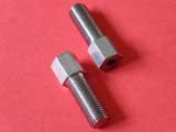
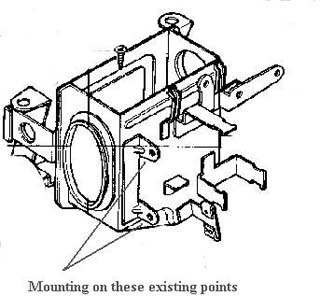
Stainless stay bolts
Try putting the headlight on full beam and then pressing the PA switch you will see evidence of the systems high resistance through all those switches and wires. The reason for such improvement is that you are halving the resistance of the bikes wiring. The original wiring is routed through the starter switch and the right hand switch gear was re-designed by Honda when the originals failed. NOTE: You will never achieve comparable results to modern lighting due to advances in reflector design, but do consider adding relays to high beam, low beam and the horn.
High intensity discharge (HID) lamp conversion – has the advantage of using only 35 watts of power, longer life and up to three times the brightness of quartz halogen lamps. The disadvantage is where to put the ballast and relay boxes and finding a reflector to allow for the 6mm deeper lamp base fitting. Make sure after fitting that the light is adjusted properly, blinding other road users is not a good idea.
Best solution is LED but it just doesn’t look right. If going down the LED road, make sure it is fully ‘E’ or DOT marked for road use. Replacing just the lamp with a Chinese H4 will blind other road users & is illegal in the UK.
Horn – The original equipment is far from adequate on todays roads. I recommend upgrading to a modern 105dB or greater, some nice chrome examples are available. FIAMM are one manufacturer of such items, I got my dual horn from the late great Hein Gericke.
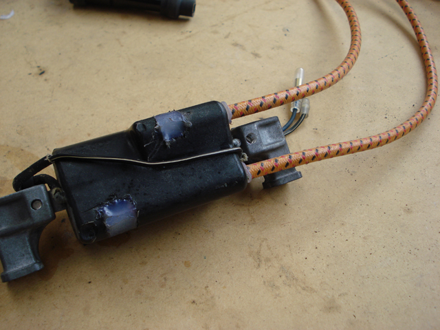
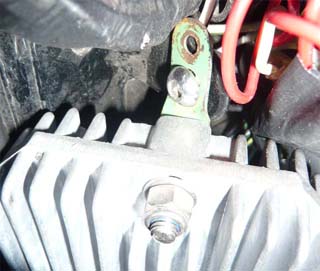
Relays – In my opinion a worthwhile improvement, giving longer life to switch gear and better lighting. All three relay modifications (horn, high beam & low beam) are easily wired into the large rubber boot under the front left on the fuel tank. Mount the relays somewhere near the left ignition coil and try to seal against moisture. All other connections were left intact to allow reversal if needed. Image shows location of my relay mods.
Relay Modifications Wiring diagram
Before starting work get a selection of crimp connectors, ideally the Japanese style and sizes. You will need male and female 3.5mm bullet connectors, get some double and triple bullet recepticles if you can find them. My relays had 6.3mm spade connections so male and female spade connectors are also useful, get some female piggy back spade connectors if you can find them. I also like the wiring to match Honda originals, a selection of colours is ideal (refer to Hondas wiring diagram).
Repairing HT coil leads – This can be done by first cutting away the old rigid PVC leads to within 15mm of the coil. 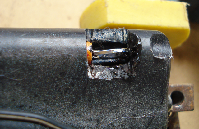
Use copper cored, i.e. not suppressed, 7mm silicone HT lead (very flexible) covered with 6mm neoprene sleeving, if you can find it. This is a swine to slide on, use of a lubricant (Hellerine oil) will help. When covered roll back on itself about 10mm of the sleeving for use later to cover the joint. Use a 1 inch long brass wood screw of suitable size with the head cut off and that end sharpened to a point. Screw in 1/2″ to the existing wire and then screw the new HT lead in to the 1/2″ thread that remains exposed. Seal the joint with silicone rubber compound and roll the sleeving forward to cover. Further waterproofing to the coil cable outlet is advisable using more silicone rubber solution. You should now have better than new water tight coils.
The coils and lead assembly are manufactured and assembled into a mould, liquid plastic is then poured in to seal the HT assembly, i.e. this is solid plastic to the actual coil itself and not just a plastic casing that can be prized open. If broken near the coil housing some of the plastic can be removed carefully with a Dremel to give enough wire to solder onto. An attempt to reveal the solder tags could be undertaken. Measured from the opposite end to the HT lead outlets, they are approx 8mm and 50mm, take care removing the plastic at these points. I tried and failed, twice!!
A better alternative is to try and find coils with a removable HT lead from another bike at your local breakers yard. CBX550, VF750 and some Kawasaki’s of the era have the same spacing for the fixing screws. This allows us to use the CB400F’s aluminium brackets for easy mounting. Originally intended for electronic ignition, 3 ohm rather than 5 ohm, they will cause premature contact point failure due to the higher current. To eliminate this use a series ballast resistor of 1 or 2 ohms and greater than 10 watts in each of the primary sides. Worth noting that the electrical capacity only just allows a halogen headlight conversion, take care when adding any extra load. Also see Electronic ignition in Accessories notes.
Testing HT coils– Secondary winding, lead to lead (1 to 4 and 2 to 3), including suppressor caps, will read approx. 25K ohms and the primary winding of each coil around 5 ohms. Coil 1 & 4 is bolted to the right hand side of the frame with 2 & 3 on the left. The length of the leads is approx. 1 = 530mm, 2 = 150mm, 3 = 230mm, 4 = 230mm. If you have no spark it is often the engine kill switch that is at fault.
Testing condensers– Using a multi meter on the capacitance scale these should measure 220nF(0.22uF). The unbranded pattern type I fitted went open circuit within ten miles resulting in a 30MPH ride home coughing and spluttering!
Suppressor caps 1&4 = NGK VD05F, 2&3 = NGK XD05F. The originals were shrouded in metal and hopeless in the wet. If fitting a Dyna ignition they recommend non suppressed leads and caps.
Spark plugs = Class 2 NGK D8EA 12mm fine pitch, 19mm reach, temperature 8 (mid). DR8EIX are the iridium type. The new Iridium spark plugs give up to 50% longer life, better starting and smoother running?, but, at a cost of around £7.50 per plug, not cheap. The NGK iridium type have an internal resistor of 5K ohms built in and some reports of poor fuel consumption unless replacing suppressor caps with non-resitor types. My first impression is less lumpy at low RPM’s allowing better drive from a standing start. Fuel consumption and top speed are about the same.
Denso standard plug is X24ES or IX24 iridium type. Although more expensive than NGK they are believed by some to be the more reliable plug, especially on a high mileage engine where wet fouling may happen. Honda use both suppliers so there can’t be much in it. Try Opie oils for Denso plugs in the U.K, they also stock oils and filters.
Rear Light on bikes of this era have only one lamp and should it fail then your rear end is left in darkness….very un nerving. Modern bikes are now being fitted with LED rear lights that are less susceptible to vibration, use less current and last 50,000 hours plus. Various replacement 1157 or BA15D LED lamps are available but are strictly not legal for road use in the UK. I have tried the 24 LED type and the results were much dimmer than the tungsten filament lamp. I then tried the superbrightleds 3W luxeon replacement, not cheap but the results are much closer to the original lamp and is the only one I would recommend.
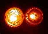


From the left, indicator with 21W lamp, indicator with 3W luxeon LED. Tail light with lamp, tail light with 3W luxeon LED, tail light with 24 hi-brightness LED’s. As clearly seen the indicator replacement is not as effective as the red tail light replacement. None of the LED’s make use of the lights internal reflector and if replacing the indicator lamps you will need to replace the flasher relay with an LED type. Any resistance from dirty switch contacts or water can cause problems when using LED’s making them flicker or even light when they should be off.
Better option would be to fit a legal backup LED device with the correct ECE marking to the lens. 50R = tested for motorcycle use, E11 = Tested for use within the UK, 11 = tested for front indicator, 12 = tested for rear indicator. Hein Gericke used to stock some nice examples, try M&P.
Indicator relay replacements are available, both LED and OE type. My OE type has connections marked L = Black +12V, X = Grey to handlebar switch & P = Green -0V. The LED type is marked B = Black +12V, L = Grey to handlebar switch & E = -0V. After buying the OE type to replace a suspected faulty relay, it turned out to be a high resistance bullet connector (grey wire) measuring around 10 ohms on the indicator switch gear.
Starter motor on my 30,000 mile example, I had 70% carbon brush wear. Removing the 3 bolts still requires the trusty impact driver. I used a lathe to turn down M6x120mm allen bolts to M5x110mm and re-threaded the ends, this should ease future removal.
New battery – After adding approximately 660mL of sulphuric acid UN2796 38% 1.28Kg/L (1.23Kg/L in tropical climates) the voltage in a discharged condition will be around 12.3 volts. A large 60mL syringe is useful here and the cells will warm as the acid is added. Stand for 15 minutes and then charge at around 1.2 amps for at least 8 hours or until 14.4 volts is reached. Wait at least 2 hours, top up each cell as necessary and it is ready to be installed on the motorcycle. Worth noting the voltage of my battery when new held up at 12.6 volts after its overnight rest.
Lithium batteries – There is likely a direct replacement from Skyrich. On another of my bikes I’ve used one for 8 years without any problem whatsoever. Much lighter in weight and longer lived than lead acid. Price is the only downside c£100
Battery testing – voltage should be 12.4V off load, put headlight on full beam and wait until 11.75V is reached. As soon as the load is turned off the voltage should quickly recover to 12.4V. If you have a hydrometer, the sulphuric acid should have a specific gravity of 1.27-1.29 (charged) and 1.13 (discharged). Well maintained a battery should last for more than 5 years. Always use a motorcycle charger at least every 3 weeks when not in use and never use a car charger, the current output is way too high. Yuasa was the original equipment supplied by Honda.
Generator – a source of problem on these bikes. The wiring goes brittle with a combination of heat and ageing. The wiring can be replaced if care is taken to strip back to where the flexible cable meets the generators coil windings. First make notes of which wire went where and take some photos if possible. I removed the resin encapsulating the two wires on the field coils using a few blows from a hammer and screwdriver, it is quite brittle and will break away. Make sure you have the replacement coloured wiring, glass sleeving, solder, epoxy resin, lacing cord and the male & female bullet connectors to hand. NOTE: it is really important to immobilise the point where the soldered joint is made as this is a weak point, you want only the flexible wire to flex and you will have a reliable repair. If the harness that exits the crankcase is also to be refurbished, make sure to keep the 8 way housing. The old blade connectors are easily removed with a jewelers screwdriver, press down on the barbed tang that hold it in place, found in a small recess at the blade side and then pulling on the wire should remove each of the seven wires. Spare blade connections are quite common, my ones were aslight bit larger in length but work fine on the bike.
FAQ – Which of the three yellow wires goes to which yellow wire on the harness? Simple answer it does not matter, the voltage here is ac and is rectified later on into a dc voltage.
Fuse box – can be a problem area. If you have a spare male 6.3mm blade terminal, try each terminal on the socket for a nice snug fit. My one had lost tension over the years and was arcing causing all manner of problems, blown fuses & lamps, wiring getting warm, over charging and possible damage to other components.
Regulator/Rectifier – I replaced both these components with an Electrex RR24 combined unit, image has the left hand side panel removed to show installation location on my machine. Finding room for the large replacement isn’t easy, I did as illustrated below.
 See the small brackets, made from old Meccano.
When testing the charging voltage I noticed it was high at 15.6 volts. I checked the +Ve sense wire and the voltage here was almost 2 volts lower than the battery voltage. Again aging electrics problem, I have fitted yet another relay to give battery voltage to the sense wire and all is well charging at exactly 14.4 volts at 4,000 RPM and above.
Neutral switch – the wire that connects this switch is held in place by a spring, simply pull the spring down, pass the wire through the small hole and release the spring.
Final Notes – the electrical/charging system on the CB400F is very limited. A 60/55W halogen headlight coupled with electronic ignition and 3 ohm ignition coils and you are at the limit of 13A. On my bike I have a 35/35W halogen lamp to ease the stress on my ageing electrics and it is used as a daylight riding lamp only.
Word has it that the CB500K1 & CB550K/F stator and coils will fit the CB400F and give over 28% increase in output @ 5,000 RPM. The wiring loom needs modification to exit the stator in the opposite direction and some models have the same output as our 400’s. Check with ohmeter for around 0.35 ohms between each yellow wire, 400/4 is 0.69 ohms. NOTE: All CB500/550 stators I’ve checked are the same as our 400/4’s so good luck trying to find the higher output one.